Introduction
One of the uses
of the op-amps in this lab is to be an integrator of an AC signal. There are
several types of signals that could be generated through the function generator.
In this lab, we will try to integrate the square, triangle, sine and sawtooth
signals and observe the output signal after it is being integrated by the
op-amps. What it means by integrated is the mathematical calculation called
integral will be done to the signals through the op-amps
Experimental
Before setting up the circuit, some predictions are made
concerning the shape of the output as shown below:
The op amps acts as an integrator since:
Vin / Rin = iC
dq/dt = C dV/dt = iC
Now in order to have V,
V = 1/(RinC) * ∫Vin(t)dt
The schematic shown in the picture above did not have an
expected result so in order to compensate for it, new values for the components
are used as shown in the table below:
|
Component
|
Nominal Value
|
Actual Value
|
|
C
|
47µF
|
46.6 ± .01µF
|
|
Rin
|
100kΩ
|
102.7 ± 0.1 kΩ
|
|
Rp
|
100MΩ
|
9.94 ± .1 MΩ
|
The setup of the circuit is as follow:
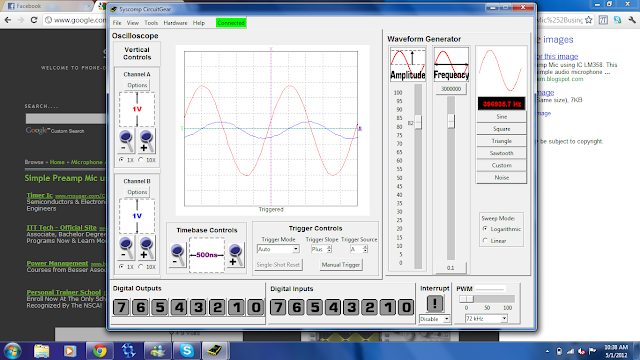
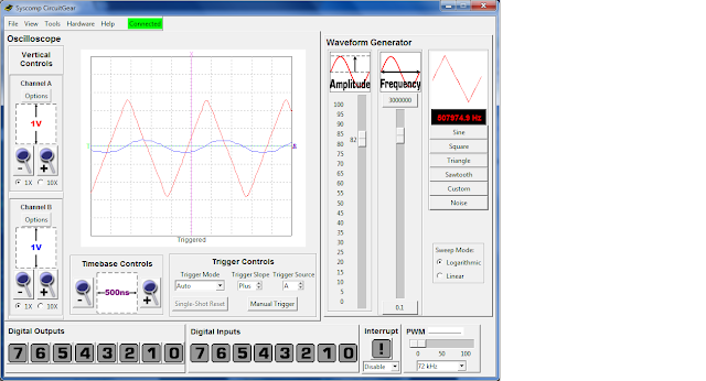
The probe is connected so that red represent the input while
blue represent the output. The result of the reading is as follow:
 |
| Sawtooth signal |
 |
| sine wave signal |
 |
| Square wave signal |
 |
| Triangle signal |
Questions:
- The 10MΩ parallel resistor is needed so that the capacitor does not saturate the low frequency signal as the resistor will take over and act as a regular op amps instead. A huge resistor is used so that the effect will be apparent when the impedance in the capacitor increased greatly.
- When integrating a constant voltage, in this case a DV voltage, it will charge the capacitor and it will make the capacitor act as an open circuit which also make all the current goes to the resistor leading to not an integrator but a regular gain op-amps.
- When the parallel resistor is taken, the capacitor will only integrate the frequency setting it designed to do and will saturate the output when its dealing with low frequency.


No comments:
Post a Comment